So first I need to start with the visual inspection:
- Double check your circuit matches your diagram.
- Is everything pushed in properly?
- Are all polarised components in the right way round?
- Are your stripped wire ends the right length? (5-10mm)
- Have any connections snapped?
- Are the values of your components correct? (resistors, capacitors etc.)
- Is your IC in the right way round?!?
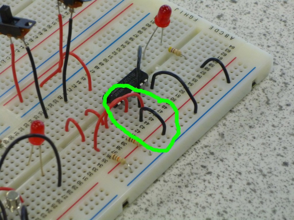
On comparing the circuit to the diagram the first fault is found!
An extra wire has been added connecting pin 1 to ground.
After removing the additional wire the circuit matches the diagram. All components are pushed in, the LED is the right way round, no snapped or short connections, all resistors are the correct values and the chip is the right way round, I’ve also double checked the pinout of the chip using the datasheet found here: TC4011BP data sheet. Time to power up…
- Is anything heating up? (Be careful!)
- Does it smell of burning?
Nothing melted and I still have all my fingers but it doesn’t work ![]() This is frustrating I’ve double checked the circuit diagram, the connections, the pinout of the chip and by all rights it should work!!
This is frustrating I’ve double checked the circuit diagram, the connections, the pinout of the chip and by all rights it should work!!
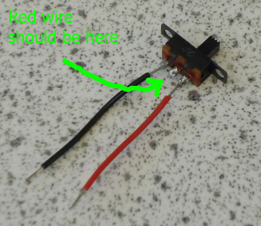
Note to self… Steve is sneaky. As all my circuits are made on breadboards I had removed all references to soldering from my original fault finding document. For this circuit I used two SPST switches, as they don’t fit straight into the board I had to solder on lead wires to the correct points. After examining the switches I can see that he’s changed the points that my wires are attached to, moving one on each off the common!
I’ve adjusted my procedure accordingly ![]()
On to Number 2.

