Starting with the visual:
- Double check your circuit matches your diagram.
- Is everything pushed in properly?
- Are all polarised components in the right way round?
- Are your stripped wire ends the right length? (5-10mm)
- Have any connections snapped?
- Are the values of your components correct? (resistors, capacitors etc.)
- Is your IC in the right way round?!?
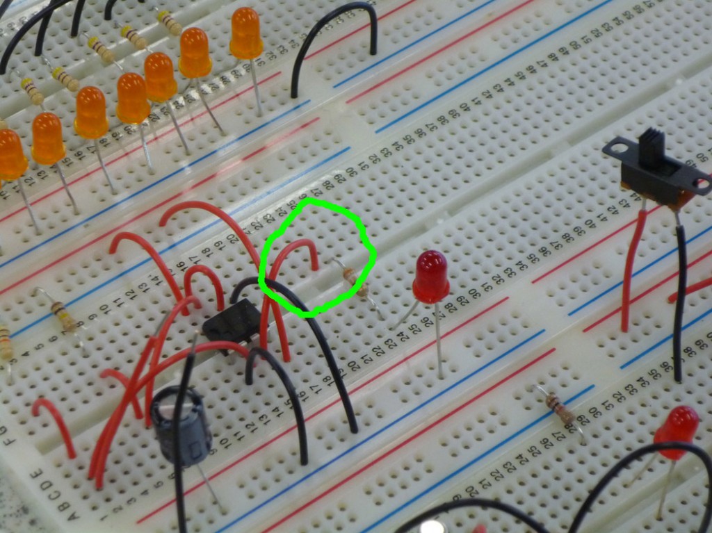
Straight off I can see that although the circuit diagram is correct the connection to the resistor and on to the LED has been moved:
As this is a breadboard circuit the connection needs to be on the same vertical line of connections as the resistor to make the connection.
All polorised components ok, all resistor values ok, the chip is in the right way round, time to power up…
- Is anything heating up? (Be careful!)
- Does it smell of burning?
No explosions ![]() Hmmm… still not working. time to do the top down checks
Hmmm… still not working. time to do the top down checks ![]()
- Top down, bottom up or split depending on type and size of circuit.
- Multimeter to check continuity and voltage values.
- Ocilloscope to check signal types and changes.
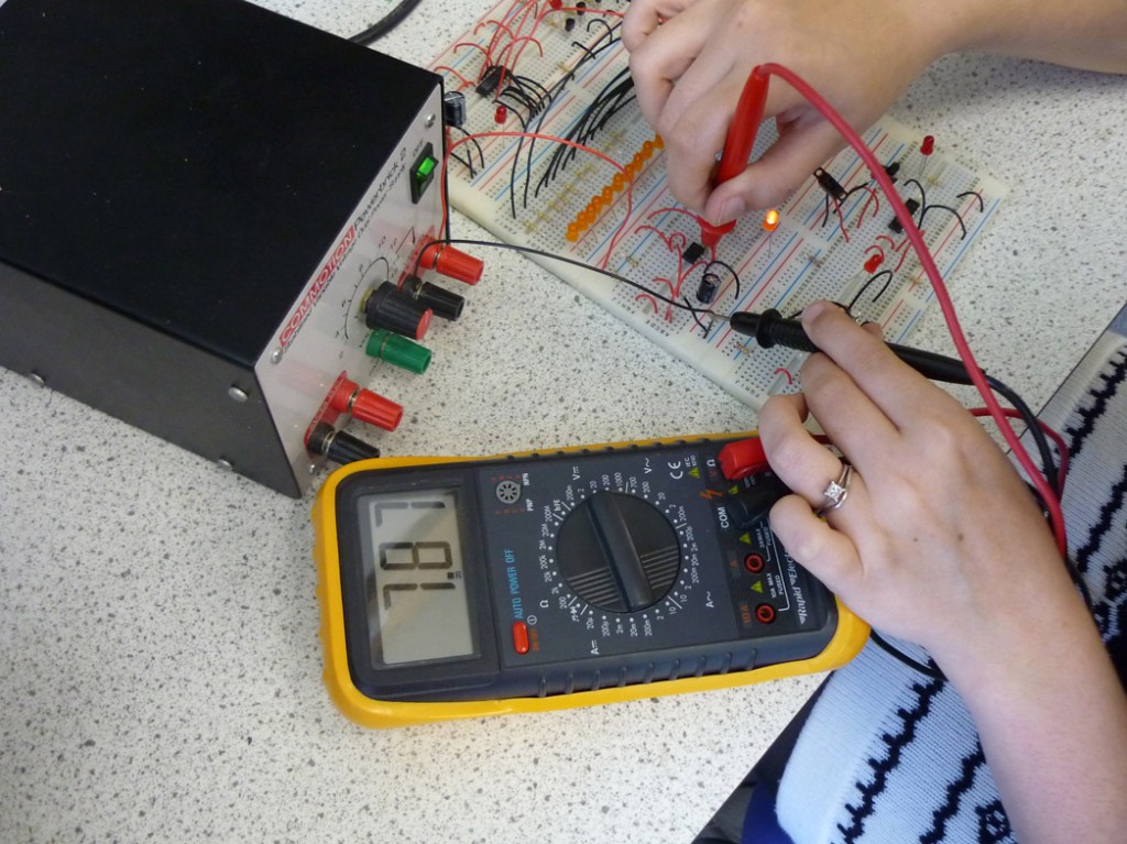
I’m using the multi meter to check the power going to and coming from each stage of the circuit using the Top Down method:
- Voltage is traveling through the switch ok
- The capacitor is charging properly
- The readout from Pin 8 is 9V as expected
- the readout from Pin 4 is 9V as expected
- Pin 1 is at 0V as expected
- Pin 2 goes high when the switch is closed
- Pin 7 follows the capacitor charge as expected
- Pin6 follows the capacitor charge as expected
This only left Pin 3 which is the output going to the LED, surprisingly this is also going high when the switch is closed, power is getting to the LED… Steve must have fried it!
Bingo, after swapping out the LED for a new one my circuit now works ![]()
On to Number 4.

