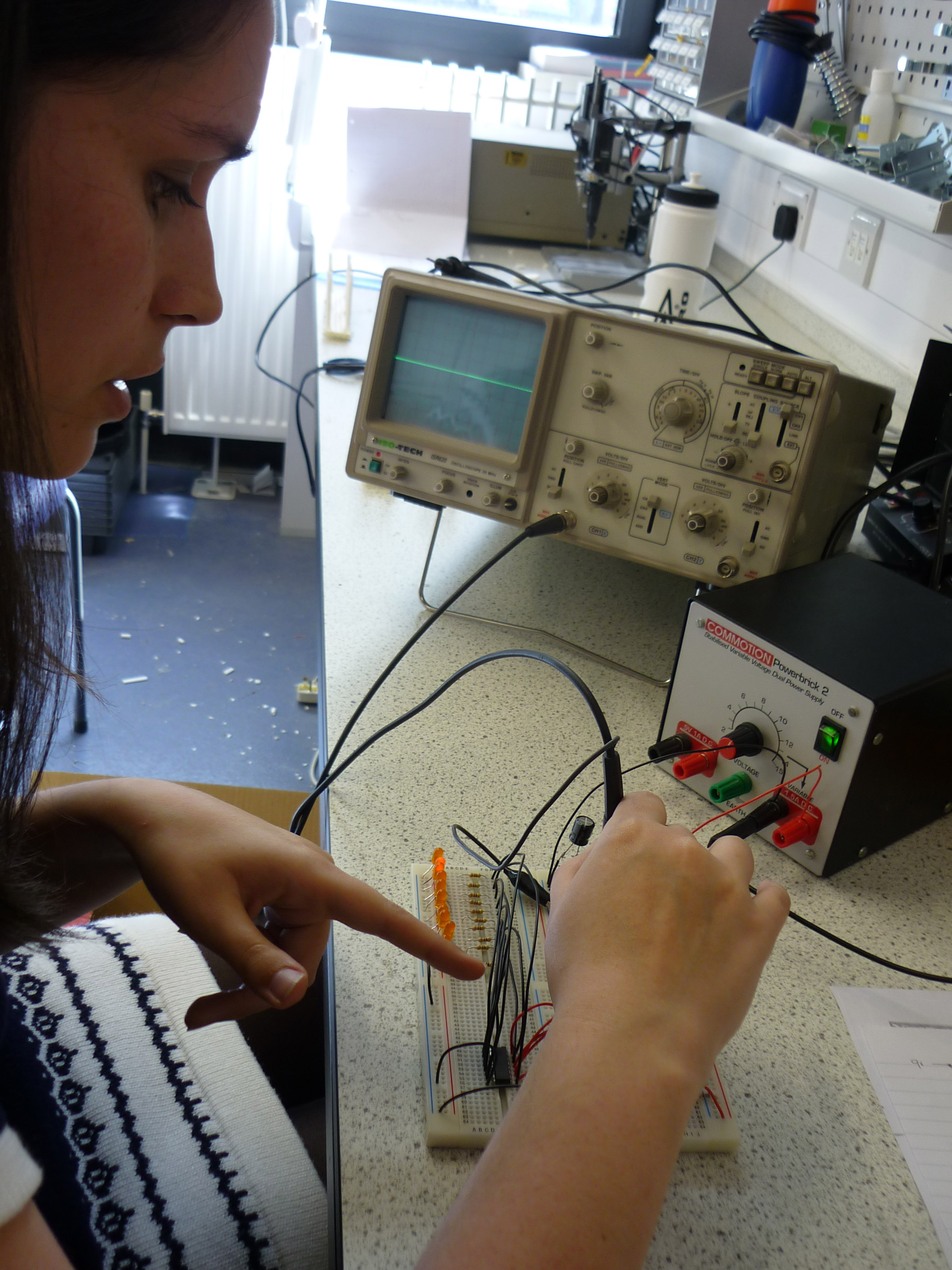
I’ll be breaking this circuit down into its 3 component parts to make the analysis a bit simpler so I’ll be looking at the signals from the astable to the binary counter and from the binary to the decimal converter. So… like the input: the pulse from the astable 55, the process: the binary counter, and the output: the decimal LED readout.
Right, last visual inspection:
- Double check your circuit matches your diagram.
- Is everything pushed in properly?
- Are all polarised components in the right way round?
- Are your stripped wire ends the right length? (5-10mm)
- Have any connections snapped?
- Are the values of your components correct? (resistors, capacitors etc.)
- Is your IC in the right way round?!?
Astable circuit: the capacitor was not pushed into the right place, all resistor values are ok, capacitor value is ok, all polorised components are placed correctly and the 555 is in the right way round.
Binary counter: I’ve checked the connections to and from the 4510 using the datasheet found here: datasheet HCF4510BE checking the pinout against the board:
- Pin 16 going high – check
- Pin 15 clock input taken from the output of the 555 timer – check
- Pin 14 going to LED output (4s) – check
- Pin 13 going to ground – check
- Pin 12 going to ground – check
- Pin 11 going to LED output (2s) – check
- Pin 10 going high – check
- Pin 9 going to ground through pull down resistor – check
- Pin 8 going to ground – check
- Pin 7 not connected – check
- Pin 6 going to LED output (1s) – check
- Pin 5 going to ground – check
- Pin 4 going to ground – check
- Pin 3 going to ground – check
- Pin 2 going to LED output (8s) – check
- Pin 1 going to ground – check
All resistor values are OK, all LEDs are in the right way round, all transistors are connected up correctly and the chip is in the right way round.
Binary to decimal counter: the chip is in the wrong way round!
Using the datasheet found here: datasheet HCF4028BE I’ve checked the pinout against the board:
- Pin 16 going high – check
- Pin 15 going to LED output (3) - check
- Pin 14 going to LED output (1) – check
- Pin 13 input taken from the binary circuit output (2s) – check
- Pin 12 input taken from the binary circuit output (4s) – check
- Pin 11 input taken from the binary circuit output (8s) – check
- Pin 10 input taken from the binary circuit output (1s) - check
- Pin 9 going to LED output (8) – check
- Pin 8 going to ground – check
- Pin 7 going to LED output (6) – check
- Pin 6 going to LED output (5) - check
- Pin 5 going to LED output (9) - wrong! it’s going to 7!
- Pin 4 going to LED output (7) - wrong! it’s going to 9!
- Pin 3 going to LED output (0) – check
- Pin 2 going to LED output (2) – check
- Pin 1 going to LED output (4) – check
The resistor values are all OK but two of the LEDs are the wrong way round. That, I think, is everything, time to power up…
- Is anything heating up? (Be careful!)
- Does it smell of burning?
Arrggg hot chip!! The 555 is roasting! I really don’t understand why it’s not working… Steve hint’s to take a closer look…
The 555 isn’t a 555! it’s a 741CN or an op-amp in English. Right swap it out and try again…
It works! Kind of ![]() The LED output representing the 1s on the binary counter isn’t working. Time to tool up.
The LED output representing the 1s on the binary counter isn’t working. Time to tool up.
- Top down, bottom up or split depending on type and size of circuit.
- Multimeter to check continuity and voltage values.
- Oscilloscope to check signal types and changes.
I’m going for the split method as I know that the input is working and some of the output is working so potentially I might have a misfiring pin. Using the oscilloscope I checked out the signals going from the 4 outputs:
As it’s the output corresponding to the 1s column it should switching high and low at a frequency half that of the pulse from the astable output. Hmmm… all the outputs are acting correctly, it must be something in the resistor, transistor LED array.
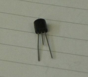
After the incident with the monstable LED I switched it out to rule out a blown LED which didn’t fix it so… It’s either a problem with the wires or the transistor. I checked the continuity of the wires using the multimeter, no problems there so it must be the transistor. On lifting it out to check the connections I found that sneaky Steve had cut the base lead off to just the right length that it looked correct from a external perspective, clever ![]()
It’s not all plain sailing though, after switching out the transistor I loudly announced that it was fixed, sounding ever so pleased with myself… that is until Steve said ‘are you sure?’ Turns out I’d missed another blown LED ![]() the one corresponding the the 0 on the decimal side. Oh well, missing one blown bulb isn’t so bad, I won’t be so cocky next time!
the one corresponding the the 0 on the decimal side. Oh well, missing one blown bulb isn’t so bad, I won’t be so cocky next time!


