Right, like linkages drive mechanisms (the collective term for pulley and gear systems) connect other mechanisms together but this time using rotary motion. This may also involve gearing or changing the angle or direction of the motion.
There are two types of drives: positive and friction. Gears fall into the positive category as they are made up of inputs and outputs locked together and synchronised. Pulleys and belts fall into the friction drive category as they rely on the friction of the belt against the pulley to transfer the movement.
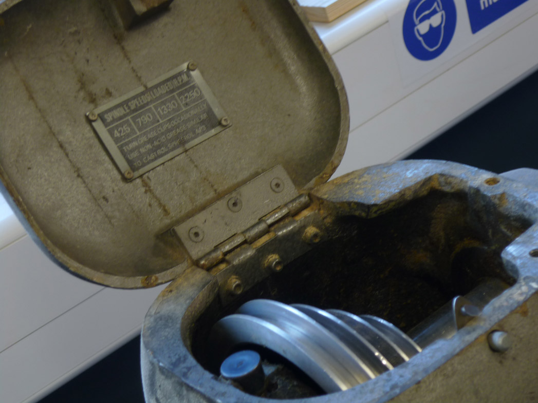
A good example of a friction drive is the inside of a wood turning lathe:
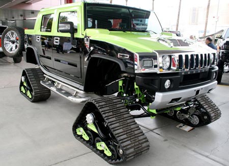
The pulleys have no teeth and the belt is driven by friction. For positive drives you can have toothed pulleys and belts or a chain an sprockets. Toothed belts have notches cut along their inside edges that engage with teeth cut in the surface of the pulley, like the rather fetching treads on this hummer tank:
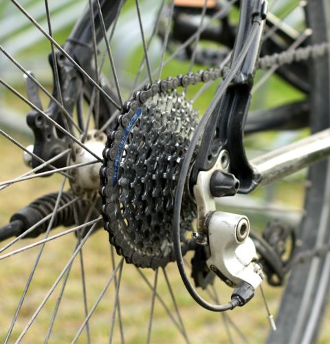
Chain and sprockets work the same way except the teeth are on a sprocket wheel and fit into the gaps in the chain, like the gears on a bicycle:
So there’s the types and some examples but what about the detailed stuff?
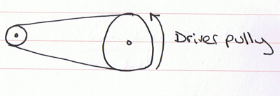
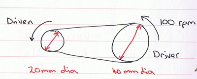
In a any drive system you have a driver gear or pulley and a driven gear or pulley, the relation ship between them is determined by their size, for example:
In this system the driven pulley , being smaller than the driver, would go much faster and have much less torque acting on it.
Where as in this system the driven pulley would go a lot slower and have more torque acting on it, the technical term for the relationship between the two is called the velocity ration and it can be worked out using another mathematical equation.
As I said in my post on mechanisms a wheel (or pulley or gear) is just like a lever that moves through 360° so your looking at the equivalent of…
distance moved by effort ÷ distance moved by load
This translates into…
distance moved by the driver pulley ÷ distance moved by the driven pulley
Which is made much easier to work out by finally turning into…
Velocity Ratio = diameter of driven pulley ÷ diameter of driver pulley
Note the driver and driven have changes places in the final equation.
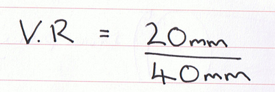
So the velocity ration for this system is 0.5:1. It works in a very similar way for geared systems:
So the velocity (gear) ratio of this system is 2:1
So what if you want to work out how fast a pulley is turning? You use the (rather long worded) equation below:
Rotary velocity of driven pulley x Diameter of driven pulley
=
Rotary velocity of driver pulley x Diameter of driver pulley
Or:
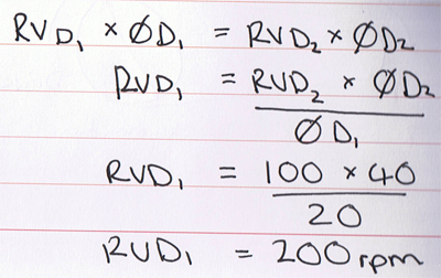
RV D1 x ØD1 = RV D2 x ØD2
So I want to find out the rotary velocity of the driven pulley here, again using the transposing formula techniques I spoke about in my previous post you end up with:
There is so much more I could go into, cams, cranks, shafts, ratchets, springs, the list is huge! I really want to get my teeth into making a mechanism so I’m going to move on and have a go at building an automata. I’ve always loved moving toys and I’ve not made one of these since I was little playing with paper kits ![]()
