In having a nosy at what my fellow students have been doing I’ve come across another digital logic device called a flip flop.
The ever helpful Steve has aslo been building a binary counter but he has done it in a very different way to mine, he has used a chain of 4 linked D type flip flops.
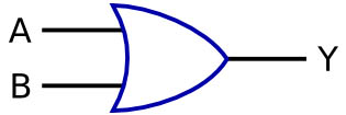
To give you a brief explanation of what I mean by D type flip flop I have to go back to my logic gates:
This OR gate looks perfectly normal but what if we…
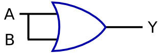
…link it’s output back through one of it’s inputs? This turns it into a digital logic with feedback device. Any digital circuit using feedback is called a multivibrator, the example I used above is a bistable multivibrator as it is stable in one of two states, you can also get monostable (one stable state) and astable (no stable state) just like the 555 timer!
The logic circuit for a D type flip flop looks like this:
The latch in the truth table looks a bit odd though… We know that a high input to a NOR gate will gove a low output, the circuit will ‘latch’ in the state after anytime that the inpit is high. When the input is low the output could be either high or low depending on the circuits prior state.
It’s quite quite simple but a little longwinded to explain fully but if you fancy finding out exactly how they work have a look here.
So a D type flip flop is a bistable multivibrator, a digital logic device using feedback with two stable states.
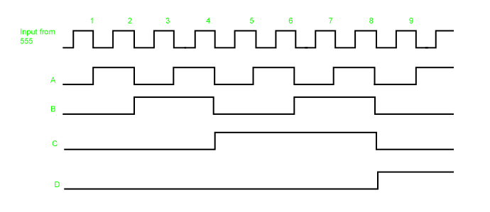
As I said before Steve has been using these to build binary counting circuits so how does that work? First you need to start by looking at the input and output of a flip flop. The input can come from something like a 555 timer astable circuit, this high, low, high, low wave form goes into the clock input and then is fed back through the data input, this results in the second wave form from output Q. The second wave form is half the frequency of the first, the flip flop divides it by two. This is really important for making the counting circuit.
When you feed the output from one chip into the clock input of another it divides the frequency in half again so the following signals will look like…
…this. Look familiar? It’s the same as the pattern of the outputs from the 4510 chip ![]() Each output fed into each subsequent chip divides the signal forming the pattern of a binary counter.
Each output fed into each subsequent chip divides the signal forming the pattern of a binary counter.
So whats the difference between the two? As I have mentioned in my post on counting circuits there are two types of counting circuit, ripple and synchronous. The arrangement of flip flops I have described above is an example of a ripple counter. It is vary simple and does work but it has it’s disadvantages. The first is there is a tiny delay as the original clock signal ‘ripples’ through the circuit and the second is that if you are using it to trigger a logic circuit it can give glitchy signals, for a ripple counter to count from 0111 (7) to 1000 (8) it will go through 0110, 0100 and 0000 before it settles on 1000, this happens too fast for us to see but not for a logic circuit.
A synchronous counter is like the one I built in my previous post.It has a much more complex structure which does the job of making sure that all the outputs change at exactly the same time on each clock pulse. It also avoids the tiny false counts so you could use them to trigger a logic system.


