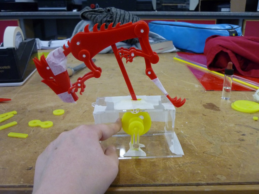
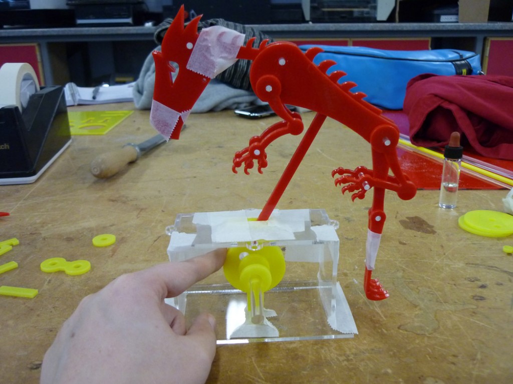
So, first, what is going to make my dragon fly?
As a said before I think that the best mechanism to replicate the movement of the Pegasus will be a crank. A crank is basically a lever attached to a rotating shaft, the diagrams below are from a great book ‘Cabaret Mechanical Movement’ by Aidan Onn and Gary Alexander, highly recommended if you want to do any work with mechanisms!
(scan of crank images, label parts)
I don’t think I’ll have enough time to cut my parts out of brass, no matter how beautiful the end result will be. To save time it would be quickest to draw the components in 2D Design and manufacture them on the laser cutter.
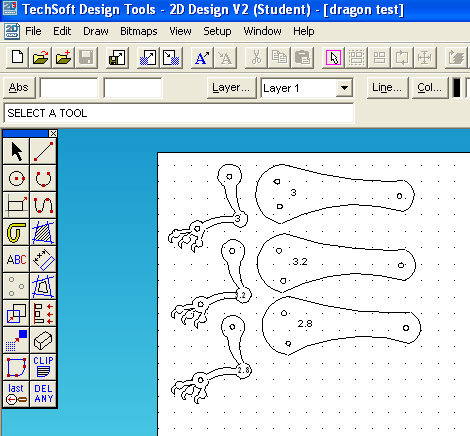
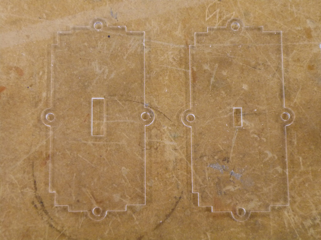
Fist things first, what do I have to make the pivots for everything to move around? Looks like I’ve got 3mm acrylic rod to work with, so what size hole do I need for this to work? I’ll need a tight fit for fixed points and one for moving points but not too loose, I don’t want any rattle:
Using 2D Design it was easy to manufacture test pieces, looks like it’ll be 3.2mm for the moving points and 3mm for the fixed points. Even though the results seem obvious you never know if the laser cutter will melt a little extra away from the cutting line, it all depends on how the machine is set up.
Next, the length of the lever connected to the dragon. This is all linked together with the size and position of the cam for the crank so…
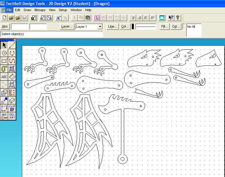
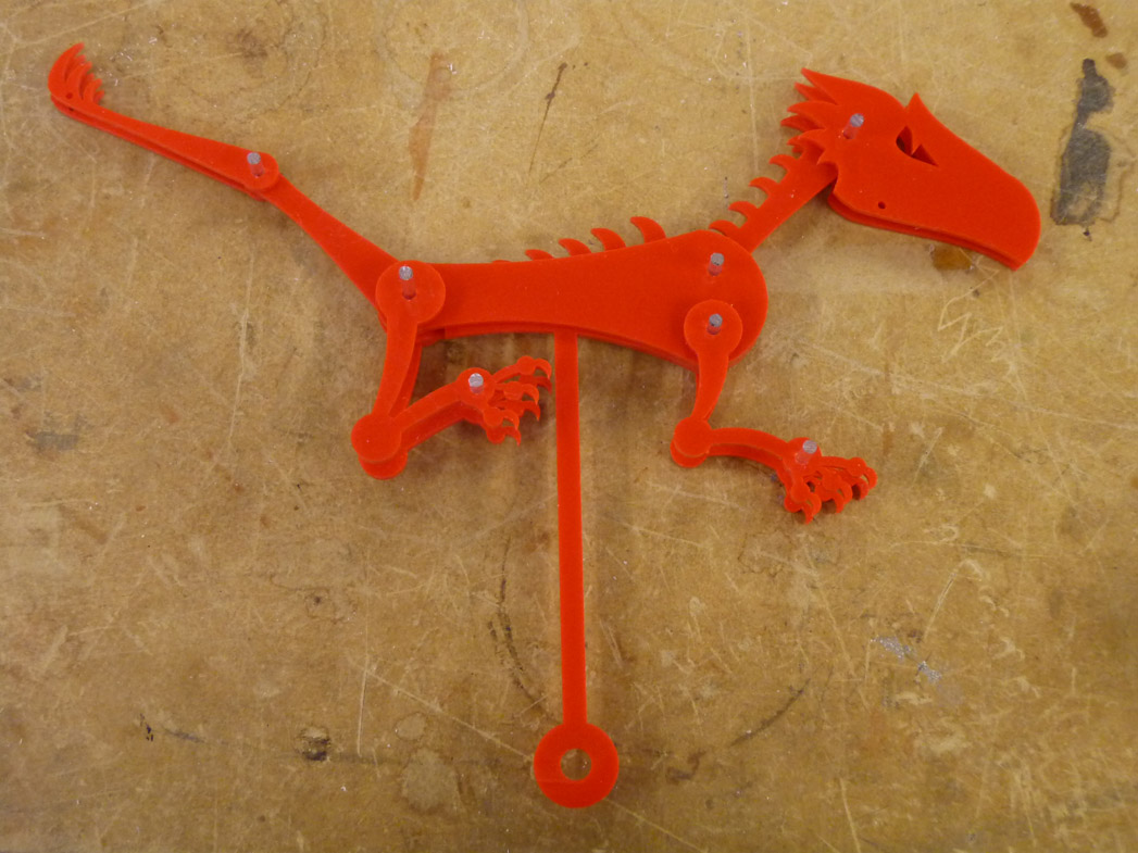
The part of the drawing to the right is an accurate representation of the dragon at it’s lowest point on the crank. There appears to be enough room for everything to move so I think I can go ahead an design the rest of the dragon:
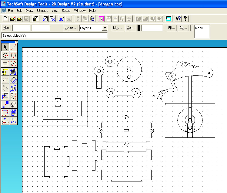
The additional pieces are all to make up the layers that move against each other. So now I have my dragon, the box size and shape and the cam drawn, I think I’m about ready to start construction!
Clang!! first problem, I’ve not left enough space for the vertical rod to fit through the top of the box! Back to the drawing board:
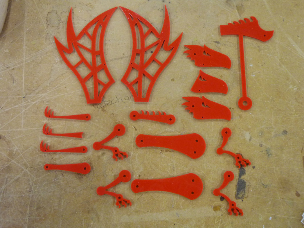
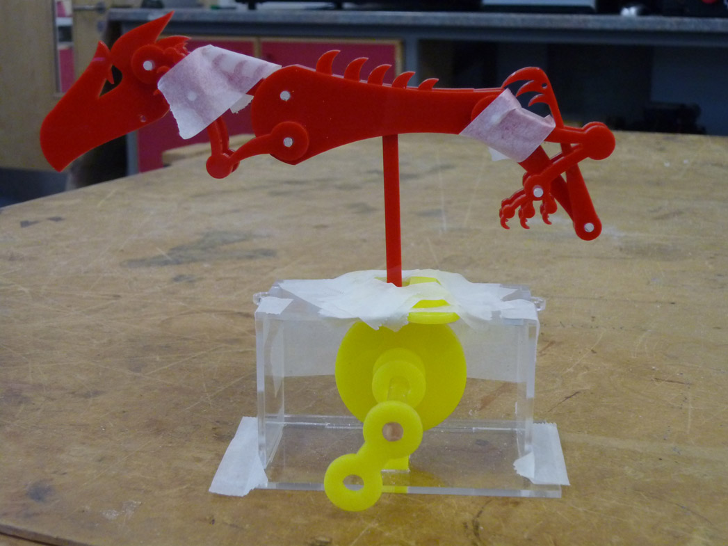
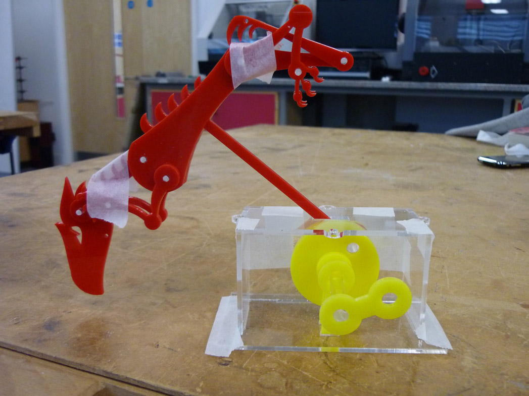
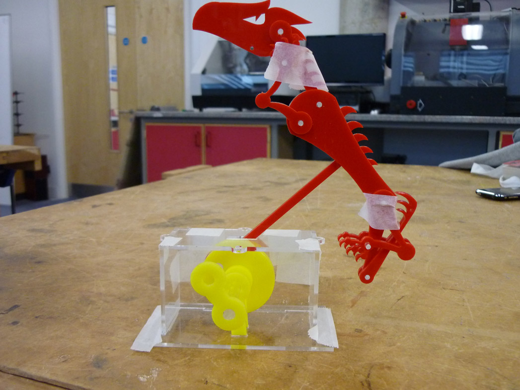
Right got there in the end, time to do a test fit:
Looking good ![]() till I tried the mechanism
till I tried the mechanism ![]()
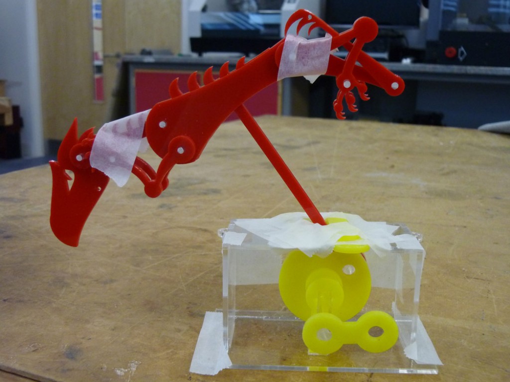
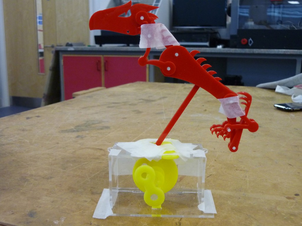
Crud, he’s all floppy and moving way too far back and forth, I tried fitting some scraps to close the hole in the top up a bit to see if it made a difference:
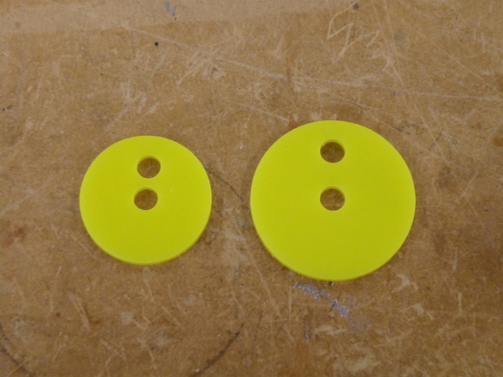
Hmm it’s a bit better but not by much, I’ll need to alter the mechanism if I’m going to make much of a difference. To reduce the ellipse that the crank describes at the top there are a few things you can do, make the cam smaller, move the shaft and pin points closer together on the cam or to move the guide higher up. As I’ve already cut the box and I don’t want to waste material re-cutting it I’m going to ry a combination of the first two:
The one on the left is my new design, I’ve also included a couple of new components to limit the size of the guide hole in the box lid, time to test again:
Much better! I’ve made the hinges for the wings out of some acrylic tube cut into three pieces, the middle stuck to the wing and the other two sides stuck to the body with a piece of rod in the middle for the pivot, to stop it falling out I ran a little acrylic cement in the end of the tube at each end. It’s still a little clunky but hopefully the linkages will reduce a lot of that.
