If I’m going to teach electronics (or even develop my interest as a hobby) there are three ICs that I will have to look at. They are the op amp (operational amplifier), the 555 timer and the 4017 decade counter.
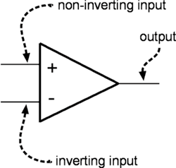
Op Amp - this IC takes a weak signal and gives it a boost, it’s made up of several transistors, resisters and capacitor. It gives a much better performance than using a single transistor. The op amp is in fact an analogue IC, it takes the input voltage through the two input leads shown below and produces an output that (and here’s where it gets technical…) is a multiple of the difference between the two inputs, so not just high and low.
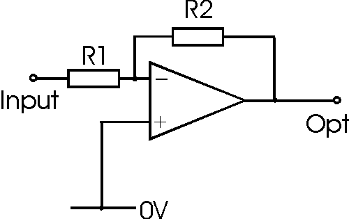
the actual gain involved can be controlled using resistors, one of these control circuits is called an inverting amplifier. The values of the resistors shown below can be used to work out the gain using this equation – Gain = R2/R1, so for instance if the resistor values were R2 = 10k and R1 = 1K the gain would be 1000/100 = 10 so a signal of 1V would produce an output of 10V.
(As this is analogue and I’m working on digital, I don’t think I need to go into any more detail to op amps at the mo.)
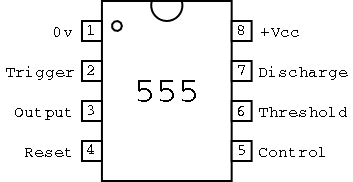
555 Timer - This popular little IC can be used in analogue and digital circuits, from my first look at them it seems there in everything. It’s well worth getting to know what each of the pins does on a 555 as it makes it easier to understand what’s going on inside. I pulled the descriptions below straight out of one of my text books:
Trigger - when you apply a low voltage to pin 2, you trigger the internal timing circuit to start working.This trigger is know as an active low trigger.
Output – The output waveform appears on pin 3.
Reset - If you apply a low voltage to pin 4, you reset the timing function, and the output (pin 3) goes low. (Some circuits don’t use the reset function, and this pin is tied to the positive supply.)
Control – If you want to override the internal trigger circuit (which you normally don’t), you apply a voltage to pin 5. Otherwise, you can connect pin 5 to ground, preferably through a 0.01µF capacitor.
Threshold – When the voltage applied to pin 6 reaches a certain level (usually two-thirds of the positive supply voltage), the timing cycle ends. You connect a resistor between pin 6 and the positive supply. The value of this timing resistor influences the length of the timing cycle.
Discharge – You connect a capacitor to pin 7. The discharge time of this timing capacitor influences the length of the timing intervals.
(Ross, Shamieh, McComb, 2010, p.153-4)
There are 3 main ways to use a 555 chip, the different configurations producing different outputs. They are…
As an astable multivibrator (oscillator) - astable just means that the output has no stable state, it doesn’t settle down but keeps changing on it’s own. You can use this for flashing lights,making an alarm or triggering a logic chip…
As amonostable multivibrator (one shot) - monostable means this circuits output has one stable state, it generates a single pulse when triggered. This state is really useful for triggering logic devices.
As a bistable multivibrator (flip flop) - bistable means (you guessed it) this circuits output has two stable states, it switches from one state to the other when it’s triggered. You can make a quiz show buzzer system using this state, it’s in it’s low state as the question is being asked, a contestant hits a button to answer triggering the high state, this is then reset in to the low state by the quiz master.
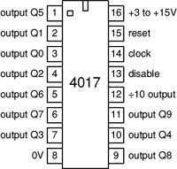
4017 CMOS Decade Counter - This cool little chip will count from 0 - 9 when it’s triggered, by joining lots of them together you can count up tens, hundreds, thousands etc you have to be careful though… the output pins are not in order down the side of the chip, you have to check the configuration in the ‘pinout’ diagram below.
4000 CMOS Series Logic Gates - I’ve kind of started looking into these gates here, but there are a couple of cool experiments I can do to physically show how gates work. I’ll put these in a later post.


