Brilliant session with Dean today, loads to add…
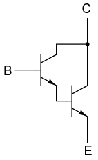
First, the Darlington driver or Darlington pair. You basically feed the emitter of one NPN transistor to the base of another, this multiplies their individual current gains so massively boosting the signal. Darlington pairs can be used like this to convert analogue signals to digital ones. If you had a potentiometer connected up to the base of the first transistor and an LED being driven from the other you can see this effect in action. Instead of the LED getting brighter or dimmer as you vary the resistance it would only switch on and off as the base current in the first transistor became high enough or low enough to affect the output of the second.
Most transistors have a threshold of 0.7V, when it the current through the base reaches this it ‘switches on’ and completes the circuit.
Note (20/03/11) Here’s a cool little circuit I put together to demonstrate a Darlington pair:
Note (20/03/11) And a look at how potentiometers work. A Potentiometer or POT is an adjustable resistor. It has 3 connections, one connects to the power source, one goes to ground and the last runs across a strip of resistive material. It acts as a wiper running across the strip which at one end has a very low resistance and the other which has a high resistance. the wiper is connected to a knob that the user can interact with.
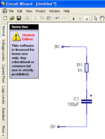
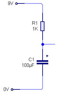
On to capacitors – a capacitor is a bit like a bucket but it collects and stores electricity not water.
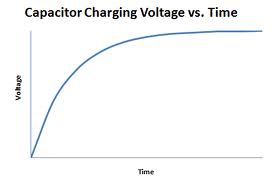
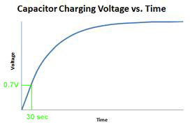
If you were to put a voltmeter across the capacitor in the circuit and plot a voltage/time graph it would look like this:
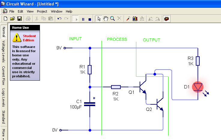
If you were to hook up a few more components to the circuit above you can convert the analogue input of the capacitor charging to a digital output:
The Darlington pair in the process part of the circuit is boosting the signal being taken as the capacitor is charging, this means that the LED will only be on or off, if the pair was replaced with a single transistor the LED would brighten or dim.
In this circuit the capacitor is acting as a delay device, as the capacitor fills the voltage increases until the required voltage to activate the transistors is reached to then turn on the LED.
So…
…this arrangement will act as a timer! You can control the time by using bigger or smaller resistors or bigger or smaller capacitors.
The equation to work out the timing is:
T=RC or Time = Resistance x Capacitance
To get a 30sec time you can work out the components you need like this:
(I’ve chosen to use a 10µf capacitor if the resistor or calculated from this was huge or tiny I could adjust this value)
30sec = R x 10µf
R = 30sec/10µf
R = 30/0.00001 (always convert your values! 10µf is actually 10-3)
R = 3,000,000Ω or 3M
This is a bit big… I could change the capacitor to a 100µf and use a 300K resistor instead
Note (20/03/11) Polorised and non polerised capacitors: Capacitors with values over 1µf tend to be polorised, meaning that the way round you connect it in a circuit matters. If you connect it the wrong way round you can cause the dielectric inside the capacitor to break down. This can short circuit the capacitor, damage other components in the circuit (by sending them too much current) or your capacitor could even explode!
Instead of using a Darlington pair you can feed this signal through a 555 timer…
