Ok, so I don’t have to create a PCB for each circuit I want to explore I’m going to have to look into methods of circuit prototyping…
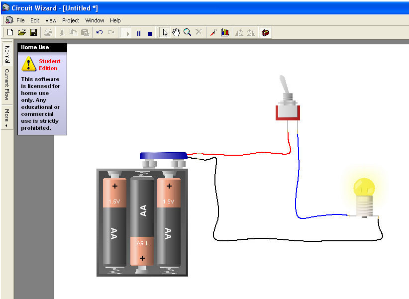
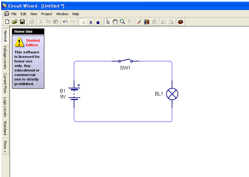
The first to come to mind (and to hand sitting at my laptop ![]() ) is a program called Circuit Wizard, I’ve already used this in previous posts to create my circuit diagrams. You can build a circuit using symbols or pictures of the components, (it’s really helpful to have a go at the pictures version with some simple circuits first if you have trouble reading circuit diagrams) this makes it easy to build up larger circuit diagrams quickly as you don’t have to spend time drawing out and labeling loads of components.
) is a program called Circuit Wizard, I’ve already used this in previous posts to create my circuit diagrams. You can build a circuit using symbols or pictures of the components, (it’s really helpful to have a go at the pictures version with some simple circuits first if you have trouble reading circuit diagrams) this makes it easy to build up larger circuit diagrams quickly as you don’t have to spend time drawing out and labeling loads of components.
This programme also has an amazingly useful function where by you can simulate applying power to your circuit. It gives you real time results of what your circuit will do (or won’t if you’ve made a mistake ![]() ) You can check that a circuit you have designed will work and do what it is intended to do without ever having to pick up a soldering iron.
) You can check that a circuit you have designed will work and do what it is intended to do without ever having to pick up a soldering iron.
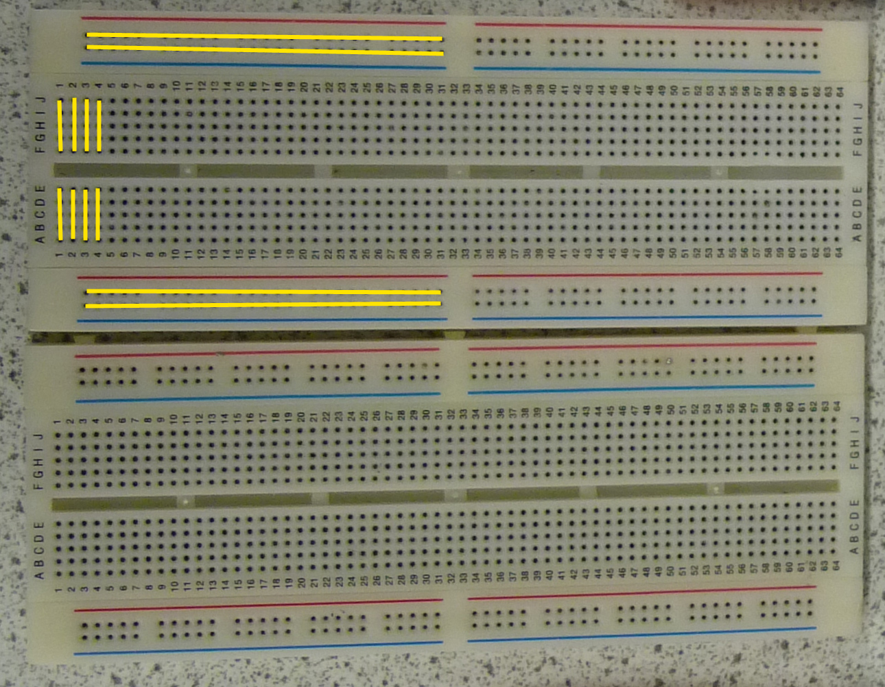
The other prototyping method I’ve been exploring is solderless Breadboards, these allow you to easily build and dismantle temporary circuits. They have hundreds of little sockets called contact holes that you can push components or wires into, these connect to metal strips running under the surface that connect groups of these contact holes into groups:
The yellow lines on the photo above show where the metal strips run: the top and bottom strips run horizontally and connect every socket in that row (they break where the red and blue lines stop), the vertical strips in the main body of the board connect up 5 sockets in a numbered row. The gap in the middle is designed for ICs to straddle, this gives you independent connections for each pin. When you poke a component lead or a wire into a socket it makes contact with the metal strip, by plugging in components and connections in the right way and running a power supply to your breadboard you can build a working circuit and because none of the components are permanently fixed it’s easy to tweak component values without the hassle of un-soldering and re-soldering. Once you’ve got your circuit working the way you want it to you can transfer it to a PCB. It’s also best to keep any circuit inputs on the left side of the board and any out puts on the right side, this keeps everything nice and neat and can be a big help when it comes to fault finding. Oh and only ever use single core wire on a breadboard, not only will multi core bend and wiggle when your trying to push it in the sockets but small bits can break off and cause shorts!
As with a perminant circuit you need to carry out a fault finding procedure before applying power. This can help prevent disasters like frying the last 555 timer you have thus condeming you to the circuit purgatory of not knowing if it would have worked after all… (shudders)
I’ve written out a little list to follow to save yourself any heartache (and possible singed fingers… eyebrows…)
- Double check your circuit matches your diagram.
- Is everything pushed in properly?
- Are all polarised components in the right way round?
- Are your stripped wire ends the right length? (5-10mm)
- Have any connections snapped?
- Are the values of your components correct? (resistors, capacitors etc.)
- Is your IC in the right way round?!?
Finally you can switch on, make sure your power supply is set to the correct voltage (never use mains on a breadboard, it could melt and you could be electrocuted!). Once power is flowing perform a powered inspection:
- Is anything heating up? (Be careful!)
- Does it smell of burning?
Hopefully you now have a working circuit, if not you need to move into the realms of circuit analysis which I’ll go into later.


