I wanted to create a couple of circuits using 555 timers and 4017 decade counters but I seem to have hit a brick wall in trying to obtain any 4017s!
Rapid look through equivalent chips with Dean and it looks like I can use a 4028 chip instead. A 4028 is officially known as a BCD (binary coded decimal) to decimal (1 of 10) decoder, this should perform the same function as the decade counter would in my counting circuits.
First I want to see if I can build a binary counter running off pulses from an astable 555 circuit, here goes…
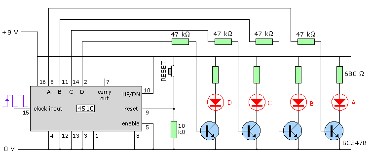
The circuit diagram is very simple, the pulses generated by the astable 555 circuit feed into a 4510 binary counter chip, this converts the input signal into the 4 output signals needed to generate the binary count, it’s much easier to see in a diagram:
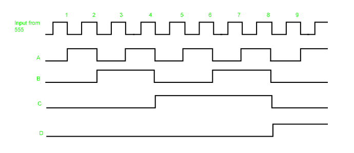
The chip uses it’s network of tiny logic gates to interpret the input from the 555 and turn it into a binary count. I find it almost easier to understand looking at these wave forms rather than truth table below, but that’s just me, I get on better with visual representations :):
| Pulses | Output D (8s) | Output C (4s) | Output B (2s) | Output A (1s) | Decimal Equivalent |
| 0 | 0 | 0 | 0 | 0 | 0 |
| 1 | 0 | 0 | 0 | 1 | 1 |
| 2 | 0 | 0 | 1 | 0 | 2 |
| 3 | 0 | 0 | 1 | 1 | 3 |
| 4 | 0 | 1 | 0 | 0 | 4 |
| 5 | 0 | 1 | 0 | 1 | 5 |
| 6 | 0 | 1 | 1 | 0 | 6 |
| 7 | 0 | 1 | 1 | 1 | 7 |
| 8 | 1 | 0 | 0 | 0 | 8 |
| 9 | 1 | 0 | 0 | 1 | 9 |
The 4510 is a BCD chip, this means that it will count a binary sequence representing the decimal numbers 0-9 hence binary coded decimal counter :)
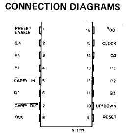
So I’ve calculated my resistor values to give me a good frequency of pulses, I’ve hooked up the 4510 according to the pinout below found in it’s data sheet (more on data sheets here) time to test.
Clang! not working! Hmmm… everything is in the right place, the two chips are hooked up properly what could be wrong… at this point enter Dean, saviour of all malfunctioning circuitry…
I hate it when it’s something really simple that I haven’t spotted, my reset switch was pushed into the board the wrong way round, *smacks head with palm of hand* and this is after Steve showed me how to use a multimeter to see how components should be connected up.
Now that’s fixed here’s the circuit working:
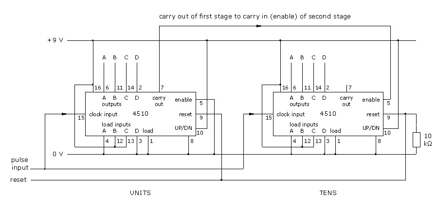
An extension of this would be to link up lots of timers together. To do this you connect the carry out (pin 7) to the carry in/enable (pin5) of another timer, this second counter now counts up 10s. By cascading them in this way you can count much larger numbers.
Note (07/04/11) There are two types of counting circuit, ripple and synchronous. The linked counters above form a synchronous counting circuit, a ripple counter is made up of linked flip flop chips. More on them here along with a more detailed look into ripple and synchronous counters.
Now I can have a go a converting the digital binary signal I have to a decimal format…
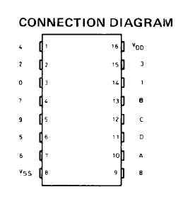
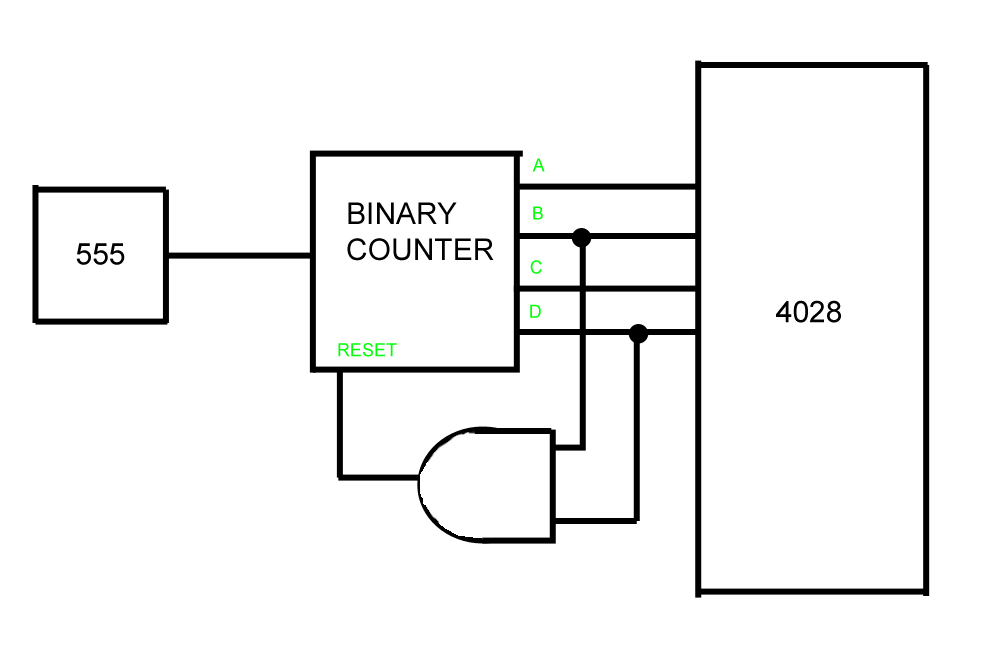
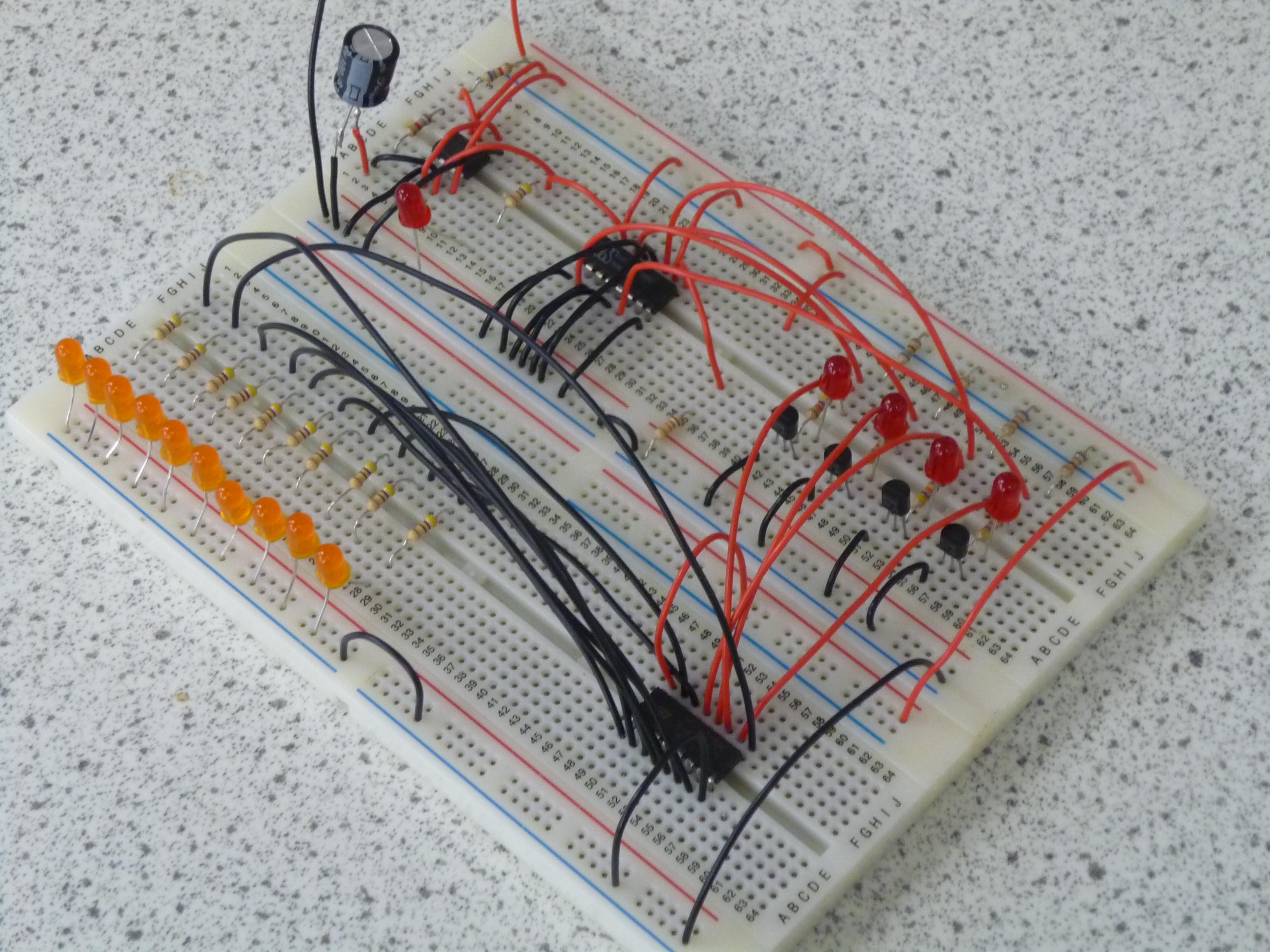
I get to have a go using the 4028 chip :) All you need to do is to hook up the 4 outputs from the binary counter to the 4 inputs of the 4028, then, carefully reading the pinout (they’re not in order as you can see below!) attach your LED outputs.
If you were using a divide by 16 binary counter you’d need to add in an extra step to limit the counter to 0-9. To do this you need to connect an AND gate using outputs B and D as the gates inputs. This would have the effect of triggering the reset every time the counter got to 10 (B and D going high together) keeping it counting from just 0 to 9.
The truth table for the 4028 is really simple, once you get past the volume of 0s and 1s the information is easy to extract:
| D | C | B | A | 0 | 1 | 2 | 3 | 4 | 5 | 6 | 7 | 8 | 9 | Decimal Equivalent |
| 0 | 0 | 0 | 0 | 1 | 0 | 0 | 0 | 0 | 0 | 0 | 0 | 0 | 0 | 0 |
| 0 | 0 | 0 | 1 | 0 | 1 | 0 | 0 | 0 | 0 | 0 | 0 | 0 | 0 | 1 |
| 0 | 0 | 1 | 0 | 0 | 0 | 1 | 0 | 0 | 0 | 0 | 0 | 0 | 0 | 2 |
| 0 | 0 | 1 | 1 | 0 | 0 | 0 | 1 | 0 | 0 | 0 | 0 | 0 | 0 | 3 |
| 0 | 1 | 0 | 0 | 0 | 0 | 0 | 0 | 1 | 0 | 0 | 0 | 0 | 0 | 4 |
| 0 | 1 | 0 | 1 | 0 | 0 | 0 | 0 | 0 | 1 | 0 | 0 | 0 | 0 | 5 |
| 0 | 1 | 1 | 0 | 0 | 0 | 0 | 0 | 0 | 0 | 1 | 0 | 0 | 0 | 6 |
| 0 | 1 | 1 | 1 | 0 | 0 | 0 | 0 | 0 | 0 | 0 | 1 | 0 | 0 | 7 |
| 1 | 0 | 0 | 0 | 0 | 0 | 0 | 0 | 0 | 0 | 0 | 0 | 1 | 0 | 8 |
| 1 | 0 | 0 | 1 | 0 | 0 | 0 | 0 | 0 | 0 | 0 | 0 | 0 | 1 | 9 |
Right, that’s the board put together, safety checks done and schematic double checked, power up ![]()
Crud! Crud! Crud! another no go! what could be wrong this time? The astable is still going, the signals to the binary are still working but the signals going to the 4028 are really weak… once again, Dean to the rescue. This time I really have had a proper brain has temporarily left the premises moment. I’d got the leads coming off the vss and vdd pins going to the opposite of where they should be. There is no excuse for this (apart from said stepping out of brain) as the data sheet clearly shows the right connections. Must slow down a bit…
Anyway now it works :)
You can take this circuit another step forward by replacing the 4028 with a seven segment display driver. It’s a very similar set up, the 4 outputs from the 4510 go into the display driver (4511) and the outputs then connect up to the inputs on the seven segment display. I may have a go at this later on but for now I think it’s time I revisited competence…
